I will post something more thorough next week, but I wanted to get some pictures and a video up for the robot I’ve been working on.
The robot was inspired by the Sparkfun IOIO: a great little board that allows you to merge the world of Android phones with the world of hobby electronics. The result? A relatively cheap robotics platform with a huge range of possibilities.
Currently the robot has two modes: a manual control mode and an autonomous, obstacle-avoidance mode. In manual mode you simply tell the motors to go forward, backwards, left or right. In obstacle-avoidance mode the robot will move forward until an obstacle is detected, at which point it will execute an “evasive maneuver” to clear the obstacle, and continue as before.
Next steps: get rosjava installed and integrated with the application. This will allow for remote control of the robot, plus remote computation like image processing of camera data.
One of my colleagues at work works remotely, and we make good use of Skype and gchat to communicate with each other. However, when he’s calling in and talking to a big group, it can be hard for him to see everyone at once unless we constantly rotate the laptop around to focus on whoever is talking. Thus I thought it would be neat for him to able to control the movement of a webcam remotely.
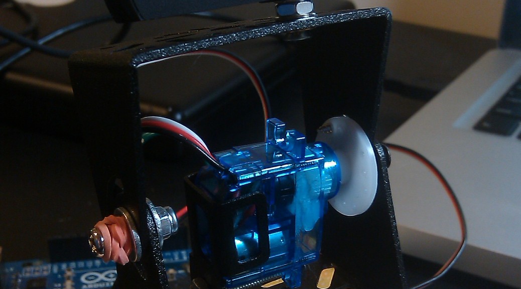
I was inspired by seeing this pan/tilt bracket from SparkFun.com. Using an Arduino would make things very easy, since it has the Servo library and built-in serial communication. As for the “remotely controlled” part, I set up an apache webserver on the local machine (apache http server is actually already installed if you’re running OSX, more on that later) that would use a CGI script to send commands to the Arduino via a serial connection.
Parts List
Webcam of your choice (I used a Logitech C510 HD Webcam) — keep in mind that you’re going to want to mount it to the pan/tilt bracket somehow
I used balsa wood (available at hardware stores and art supply stores–that is, pretty much everywhere) and wood glue to provide a mount for the pan servo. This is probably the cheapest and most low-tech approach, but you could of course use any material you like.
For mounting the camera, I pulled the camera part from the base and then screwed this on to the top of the pan/tilt bracket. Again, this will depend on your camera. Some cameras, like the Microsoft LifeCam VX-3000 Webcam, have screw-on bases and thus make this part pretty easy.
Arduino connections
I wanted to keep things modular, so to connect the servos to the Arduino I installed 2 3-pin male headers on a PC board. I wired wires going from the servo signal pins to Arduino pins 8 and 9, and from the power pins to Arduino pins GND and +5V. I also threw in an LED in parallel with the power as an extra indicator that the board was plugged in and powered.
Once you’ve uploaded the following code to your Arduino, you should be able to control the pan/tilt unit via the Serial Monitor.
#include <Servo.h>

Servo pan_servo;
Servo tilt_servo;
int incomingByte;

void setup()
{
 // attach the servos and startup the serial connection
 pan_servo.attach(9);
 tilt_servo.attach(8);
 Serial.begin(9600);
 resetAll();
}

void loop()
{

 // check to see if something was sent via the serial connection
 if (Serial.available() > 0) {
 incomingByte = Serial.read();

 // move the servos based on the byte sent
 if (incomingByte == 'e') {
 moveServo(tilt_servo, 1);
 } else if (incomingByte == 'x') {
 moveServo(tilt_servo, -1);
 } else if (incomingByte == 'd') {
 moveServo(pan_servo, 1);
 } else if (incomingByte == 's') {
 moveServo(pan_servo, -1);
 } else if (incomingByte == 'r') {
 resetAll();
 } else if (incomingByte == '/') {
 Serial.println("pan: " + pan_servo.read());
 Serial.println("tilt: " + tilt_servo.read());
 }
 }

}

// move the servo a given amount
void moveServo(Servo servo, int delta) {
 int previousValue = servo.read();
 int newValue = previousValue + delta;
 if (newValue > 180 || newValue < 30) {
 return;
 }
 servo.write(newValue);
}

// put the servos back to the "default" position
void resetAll() {
 reset(pan_servo);
 reset(tilt_servo);
}

// put a servo back to the "default" position (100 deg)
void reset(Servo servo) {

 int newPos = 130;
 int previousPos = servo.read();
 if (newPos > previousPos) {
 for (int i=previousPos; i<newPos; i++) {
 servo.write(i);
 delay(15);
 }
 } else {
 for (int i=previousPos; i>newPos; i--) {
 servo.write(i);
 delay(15);
 }
 }

}
wget http://todbot.com/arduino/host/arduino-serial/arduino-serial.c

gcc -o arduino-serial arduino-serial.c

# test moving the camera up and to the right

./arduino-serial -b 9600 -p /dev/tty.usbmodem3d11 -s dddddddddddddddeeeeeeeeeeeeeee
Running the script via Apache HTTP Server
At this point, someone could ssh in to the computer running the camera and control it via the command line, but I wanted to have a slightly more sophisticated interface. I decided to go with a simple jQuery-powered web page that hits a CGI script served up by apache. (Note: of course, if you want people to be able to control the camera from outside your local network, you’ll need a static IP address for your machine. In that case, you should probably also make sure you set up basic authentication for your apache server.)
If you’re running OSX, apache is already installed. You can start it up by running sudo apachectl start, the config is located at /etc/apache2, and the DocumentRoot points to /Library/WebServer/ by default.
cd /Library/Webserver/CGI-Executables
vim pan-tilt.cgi
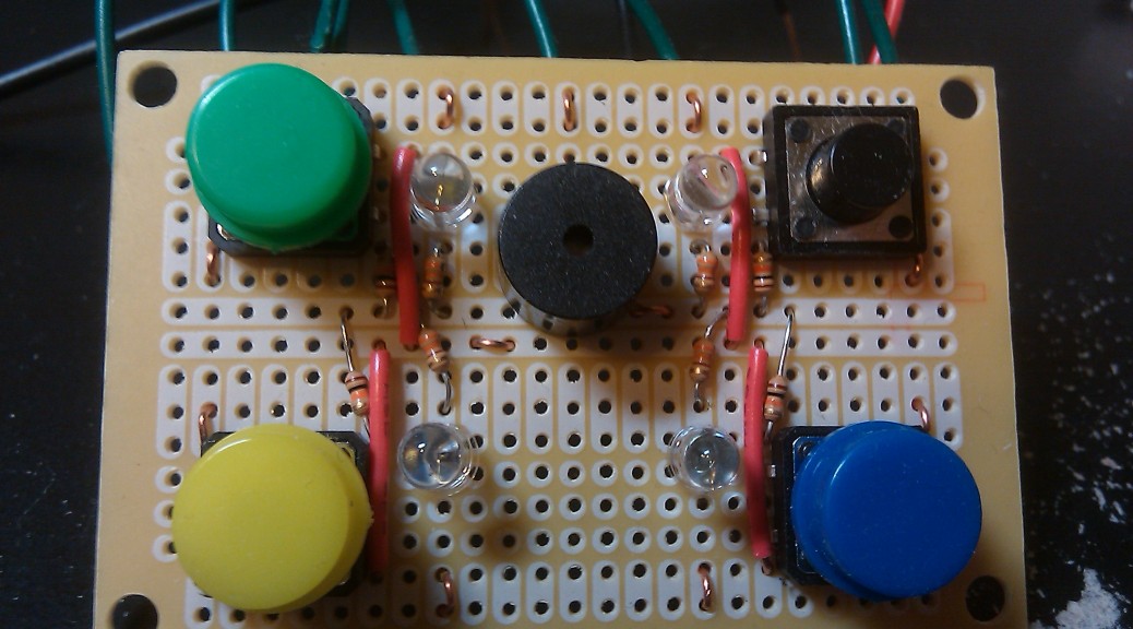
The buttons are wired to pins 5-8 with one node connected to +5V and the other to ground via a 10k ohm pull-down resistor. The LEDs to pins 10-13, with 330 ohm current limiting resistor. The piezo buzzer is connected directly to pin 9 and ground. For the wires going to the Arduino pins, I just wired one end to the board and left the other end hanging, so it is not permanently attached to the Arduino.
Code
For more information about working with the piezo buzzer and an Arduino, check out CIRC06 at ardx.org
// Whether we're in "listen" or "playback" mode
boolean listen;

// Change this value to increase or decrease the number of rounds
// played before winning the game
const int num_rounds = 9;

const int speakerPin = 9;
// "A" note frequency
const int a = 1136;
// how long to play a note
const int timestep = 500;

char buttons[] =   { 'y', 'b', 'r', 'g' };
int button_pins[] = { 5,   6,   7,   8 };
int led_pins[] =    { 10,  11,  12,  13 };
// The frequency of all other notes is based off the "A" note
// See: http://en.wikipedia.org/wiki/Simon_(game)#Gameplay
int notes[] = { a * 1.25 * 1.25,
a * 1.25,
a,
a * 0.75
};
// The note we play for failure
const int fail_note = a * 4;

// an array of the buttons for this game
int play_buttons[num_rounds];

// which round are we currently playing?
int currentRound;
// what button are we on for the current round
int current_button;

// Set up the LEDs and buzzer as output,
// and the buttons as input
void setup() {
pinMode(speakerPin, OUTPUT);
for (int i=0; i<4; i++) {
pinMode(button_pins[i], INPUT);
pinMode(led_pins[i], OUTPUT);
}

initialize();
}

void loop() {
if (listen) {
int buttonPress = readButtons();

// Check whether a button was pressed
if (buttonPress != -1) {

// make the button sound and light up the LED, to provide feedback
playButton(buttonPress, timestep/2);

// They hit the appropriate button
if (buttonPress == play_buttons[current_button]) {
delay(timestep);

// They just played the final button for the final round
if (current_button == num_rounds) {
win();
return;
}

// They just played the final button for this round
// Reset the round and switch to "playback" mode
if (current_button == currentRound) {
current_button = 0;
currentRound++;
listen = false;
return;
}

// They're still in the middle of this round
// Increment the current button and wait for next input
current_button++;
} else {  // they didn't hit the correct button!
fail();
return;
}
} // end listen
} else { // play all buttons for the round
if (currentRound == num_rounds) {
win();
return;
} else {
// playback all the buttons for this round
for (int i=0; i<=currentRound; i++) {
playButton(play_buttons[i]);
delay(timestep/2);
}
// switch to "listen" mode
listen = true;
}
}
}

// During initialization, randomly choose arrays of buttons
// for each round, then play a button pattern to let the user know
// that the game has been loaded
void initialize() {
delay(timestep*2);

randomSeed(analogRead(0));
for (int i=0; i<num_rounds; i++) {
play_buttons[i] = (int)random(0, 4);
}
listen = false;
currentRound = 0;
current_button = 0;

spin_colors();
spin_colors();

delay(timestep*2);
}

// Play the "failure" tone and restart the game
void fail() {
playTone(fail_note, timestep * 4);
delay(timestep*2);
initialize();
}

// Play the "win" button pattern and restart the game
void win() {
for (int i=0; i<4; i++) {
spin_colors();
}
delay(timestep*2);
initialize();
}

void spin_colors() {
for (int i=0; i<4; i++) {
playButton(i, timestep/4);
delay(timestep/4);
}
}

void playButton(int color) {
playButton(color, timestep);
}

// Turn on the LED and play the button's tone
void playButton(int color, int duration) {
digitalWrite(led_pins[color], HIGH);
playTone(notes[color], duration);
digitalWrite(led_pins[color], LOW);
}

// Play the buzzer at the tone's frequency
void playTone(int tone, int duration) {
for (long i = 0; i < duration * 1000L; i += tone * 2) {
digitalWrite(speakerPin, HIGH);
delayMicroseconds(tone);
digitalWrite(speakerPin, LOW);
delayMicroseconds(tone);
}
}

// Iterate over all the buttons and check if one was pressed
int readButtons() {
for (int i=0; i<4; i++) {
if (digitalRead(button_pins[i]) == HIGH) {
return i;
}
}
return -1;
}
This weekend I worked on a fun little project: an “electronic die”. You press the button and it randomly cycles through possible die rolls, eventually “landing” on a number.