Category Archives: Arduino

OpenCV Blob Tracker

github code is here!

The Blob Tracker is a simple demo that shows how you can track a certain color in OpenCV.

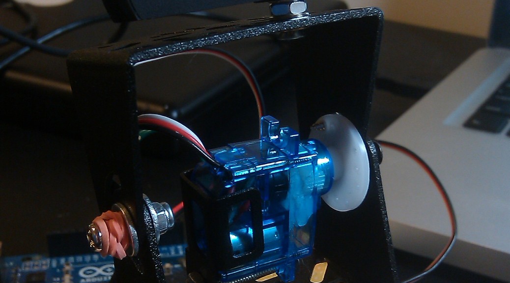
The setup consists of a camera mounted on a pan-tilt unit that’s wired to an Arduino. The camera and Arduino are hooked up to a computer via USB. On the computer, a simple Python script takes in the camera images, processes them using OpenCV, and sends back commands to the Arduino to move the pan-tilt servos and track the desired color.

Parts List and Assembly

This tutorial builds off the Remotely Controlled Pan-Tilt Unit post. Follow instructions there to assemble the unit, and upload the provided Arduino code to your Arduino.

If you’ve done things correctly, you should be able to view images from the camera on your computer (using any webcam software, like Skype or Google hangouts), and control the pan-tilt unit by plugging in your Arduino and sending commands over serial.

Installing OpenCV

In Linux, install OpenCV by running:


# run apt-cache search opencv-core first, to see which version is available. Anything greater than 2.2 should work
sudo apt-get install opencv-core2.4

Alternatively, you can install ROS, which comes with OpenCV.

Code

The code is available on Github at https://github.com/jessicaaustin/robotics-projects/tree/master/blob-tracker

Understanding color tracking

(Note: If you’re lazy and just want to track a color without understanding how it works, you can skip this section and pass in –red, –green, or –blue to blob-tracker.py below)

Most of the time, we think in terms of the RGB color model. However, when it comes to trying to track an object of a certain “color”, the RGB space is not very useful. That’s because something that’s “red” in one lighting condition might look like “dark red” in low light or “light red” in bright light.

An alternative is the HSV color model. HSV stands for Hue, Saturation, and Value. The hue is what we care about — for example, red — and the range we’ll look for here will be fairly narrow. Saturation and value will depend on the object’s texture and lighting conditions, and we can set those those values to a wider range to account for a wider range of texture and lighting conditions.

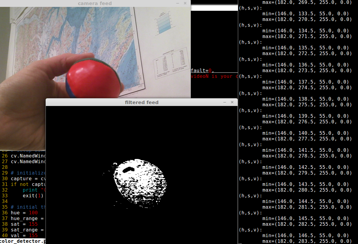
To illustrate this concept to yourself, try running the color_detector.py script in the blob-tracker folder:


# use --camera=N to set the index of your camera.
# e.g., if /dev/video1 is your camera device, then use --camera=1
./color_detector.py --camera=1

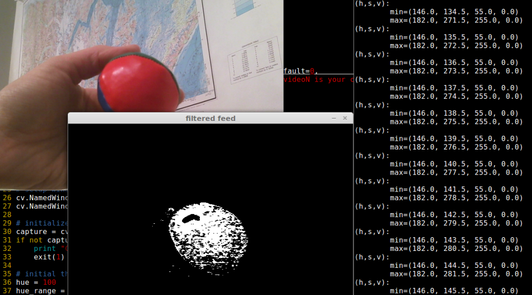
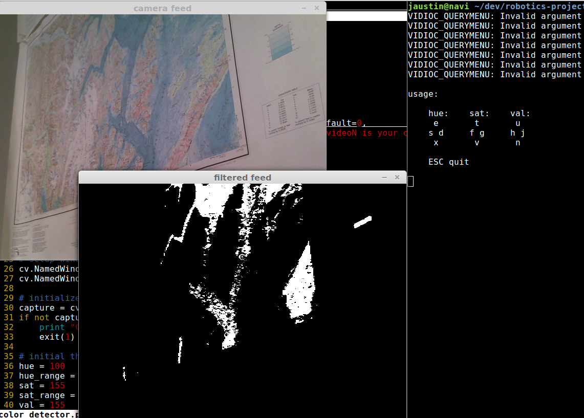
The program will pop up two windows: “camera feed” and “filtered feed”. The filtered feed is a mask where white is the color you’re tracking, and black is not.

color_detector_1

The program will start out with HSV set to the following values:
H = 100 +/- 50
S = 155 +/- 200
V = 155 +/- 200

Place a solid-color object in front of the camera — for example, a red ball — and use the keyboard to modify these ranges:

hue: sat: val:
 e    t    u
s d  f g  h j
 x    v    n

For example, to increase the max hue, press e, to decrease the min hue press x, to decrease the range press s, to increase the range press d. (If things aren’t working, make sure you have the window called “filtered feed” selected when you press the buttons).

Play with the values until you’re consistently seeing just the color you want, and not anything else (for example, a red jacket in the background).

color_detector_2

Now try changing the lighting conditions. How does this change the track-ability? What if you modify the sat and val values?

The program will spit out the current HSV min/max ranges to the terminal. Once you’re happy with your ranges, hit ESC to exit and save the HSV values — you’ll need to input them into the blob-tracker program next.

For example, for tracking a red object I ended up with:

(h,s,v):
min=(146.0, 146.5, 55.0, 0.0)
max=(182.0, 283.5, 255.0, 0.0)

Running everything together

At this point you’ve got a camera to capture images, mounted on a pan-tilt unit that you can control over serial. You also have an HSV range to track. Now it’s just a matter of running the blob-tracker code! This code will process the images, find the color you want to track in the image, and send commands to the servos to close the loop and track the color.

To run:

# get options
./blob-tracker.py --help
# find a red object (no tracking), using a camera on /dev/video1 and an arduino on /dev/ttyACM0
./blob_tracker.py --camera=1 --red
# track a red object:
./blob_tracker.py --camera=1 --device=/dev/ttyACM0 --red --follow

First try without the –follow command. You should see two windows pop up: “camera” and “threshed”. The code performs some filtering on the image to reduce noise, so the color blob in the threshed image is “smooth”. A red circle on the camera shows where the center of the largest “blob” matching your color is located. If there is more than one “blob” of the same color in the image, the code will find the largest one and track it.

blob_tracker_1

Now try running with the –follow command. Your pan-tit unit should move around the track the object!

blob_tracker_follow_3 blob_tracker_follow_2 blob_tracker_follow_1

Chicago GTUG Presentation: Building Robots with the Sparkfun IOIO


Last night I presented at the Chicago GTUG. It was held at 1871 in Merchandise Mart, and wow is that a great space! It was a real pleasure to talk there.

Here’s a link to the presentation: https://docs.google.com/presentation/d/1id7sUVDHFXhKzujg3dPWivC3kM5o3r7NIrWkq3IB_Ws/edit

Links to references from the presentation:


Remotely controlled pan/tilt camera unit


One of my colleagues at work works remotely, and we make good use of Skype and gchat to communicate with each other. However, when he’s calling in and talking to a big group, it can be hard for him to see everyone at once unless we constantly rotate the laptop around to focus on whoever is talking. Thus I thought it would be neat for him to able to control the movement of a webcam remotely.
I was inspired by seeing this pan/tilt bracket from SparkFun.com. Using an Arduino would make things very easy, since it has the Servo library and built-in serial communication. As for the “remotely controlled” part, I set up an apache webserver on the local machine (apache http server is actually already installed if you’re running OSX, more on that later) that would use a CGI script to send commands to the Arduino via a serial connection.

Parts List

Assembling the pan/tilt unit

Assembly was pretty straightforward, using the instructions on SparkFun’s product page.


I used balsa wood (available at hardware stores and art supply stores–that is, pretty much everywhere) and wood glue to provide a mount for the pan servo. This is probably the cheapest and most low-tech approach, but you could of course use any material you like.


For mounting the camera, I pulled the camera part from the base and then screwed this on to the top of the pan/tilt bracket. Again, this will depend on your camera. Some cameras, like the Microsoft LifeCam VX-3000 Webcam, have screw-on bases and thus make this part pretty easy.

Arduino connections

I wanted to keep things modular, so to connect the servos to the Arduino I installed 2 3-pin male headers on a PC board. I wired wires going from the servo signal pins to Arduino pins 8 and 9, and from the power pins to Arduino pins GND and +5V. I also threw in an LED in parallel with the power as an extra indicator that the board was plugged in and powered.

Arduino Code

githubblack Code available at Github here: https://github.com/jessicaaustin/robotics-projects/tree/master/pan-tilt-unit

Once you’ve uploaded the following code to your Arduino, you should be able to control the pan/tilt unit via the Serial Monitor.

#include <Servo.h> 
 
Servo pan_servo;
Servo tilt_servo;
int incomingByte;
 
void setup()
{
 // attach the servos and startup the serial connection
 pan_servo.attach(9);
 tilt_servo.attach(8);
 Serial.begin(9600);
 resetAll();
}
 
void loop()
{
 
 // check to see if something was sent via the serial connection
 if (Serial.available() > 0) {
 incomingByte = Serial.read();
 
 // move the servos based on the byte sent
 if (incomingByte == 'e') {
 moveServo(tilt_servo, 1);
 } else if (incomingByte == 'x') {
 moveServo(tilt_servo, -1);
 } else if (incomingByte == 'd') {
 moveServo(pan_servo, 1);
 } else if (incomingByte == 's') {
 moveServo(pan_servo, -1);
 } else if (incomingByte == 'r') {
 resetAll();
 } else if (incomingByte == '/') {
 Serial.println("pan: " + pan_servo.read());
 Serial.println("tilt: " + tilt_servo.read());
 }
 }

}
 
// move the servo a given amount
void moveServo(Servo servo, int delta) {
 int previousValue = servo.read();
 int newValue = previousValue + delta;
 if (newValue > 180 || newValue < 30) {
 return;
 }
 servo.write(newValue);
}
 
// put the servos back to the "default" position
void resetAll() {
 reset(pan_servo);
 reset(tilt_servo);
}
 
// put a servo back to the "default" position (100 deg)
void reset(Servo servo) {
 
 int newPos = 130;
 int previousPos = servo.read();
 if (newPos > previousPos) {
 for (int i=previousPos; i<newPos; i++) {
 servo.write(i);
 delay(15);
 }
 } else {
 for (int i=previousPos; i>newPos; i--) {
 servo.write(i);
 delay(15);
 }
 }
 
}

Controlling the Arduino via a script

I used todbot‘s arduno-serial.c program to control the Arduino via the command line.

Get arduino-serial.c and test it out:


wget http://todbot.com/arduino/host/arduino-serial/arduino-serial.c

gcc -o arduino-serial arduino-serial.c

# test moving the camera up and to the right

./arduino-serial -b 9600 -p /dev/tty.usbmodem3d11 -s dddddddddddddddeeeeeeeeeeeeeee

Running the script via Apache HTTP Server

At this point, someone could ssh in to the computer running the camera and control it via the command line, but I wanted to have a slightly more sophisticated interface. I decided to go with a simple jQuery-powered web page that hits a CGI script served up by apache. (Note: of course, if you want people to be able to control the camera from outside your local network, you’ll need a static IP address for your machine. In that case, you should probably also make sure you set up basic authentication for your apache server.)

If you’re running OSX, apache is already installed. You can start it up by running sudo apachectl start, the config is located at /etc/apache2, and the DocumentRoot points to /Library/WebServer/ by default.

cd /Library/Webserver/CGI-Executables
vim pan-tilt.cgi

pan-tilt.cgi is the following ruby script:

#!/opt/local/bin/ruby

query_string=`echo $QUERY_STRING`

if query_string.length != 0
`/opt/local/bin/arduino-serial -b 9600 -p /dev/tty.usbmodem3d11 -s #{query_string}`
result=`echo $?`
result=result.gsub(/n/,"")
end

print "Content-type: application/jsonnn"
print "{"result": "#{result}"}n"

Finally, create the web page:

cd /Library/Webserver/Documents
vim pan-tilt.html

pan-tilt.html:


<script src="http://ajax.googleapis.com/ajax/libs/jquery/1.5.1/jquery.min.js"></script>
<script>// <![CDATA[
            // send the input to the cgi script
            // note: sending 3x the input for every keypress, to make the movement smoother
            var submitInput = function(input) {
                $.post("/cgi-bin/pan-tilt.cgi?" + input + input + input);
            };

            // submit input when someone presses a key down
            $(document).keydown(function(event) {
                console.log(event.keyCode);
                switch(event.keyCode) {
                   case 82:
                    submitInput('r');
                    break;
                  case 83:
                    submitInput('s');
                    break;
                  case 68:
                    submitInput('d');
                    break;
                  case 69:
                    submitInput('e');
                    break;
                  case 88:
                    submitInput('x');
                    break;
                  case 37:
                    submitInput('s');
                    break;
                  case 39:
                    submitInput('d');
                    break;
                  case 38:
                    submitInput('e');
                    break;
                  case 40:
                    submitInput('x');
                    break;
                  default:
                }
            });
        
// ]]></script>

&nbsp;
<h1>Pan/Tilt Camera Control</h1>
<div>
<table>
<tbody>
<tr>
<td></td>
<td>&amp;amp;uarr;</td>
<td></td>
</tr>
<tr>
<td>&amp;amp;larr;</td>
<td>r</td>
<td>&amp;amp;rarr;</td>
</tr>
<tr>
<td></td>
<td>&amp;amp;darr;</td>
<td></td>
</tr>
</tbody>
</table>
<table>
<tbody>
<tr>
<td></td>
<td>e</td>
<td></td>
</tr>
<tr>
<td>s</td>
<td>r</td>
<td>d</td>
</tr>
<tr>
<td></td>
<td>x</td>
<td></td>
</tr>
</tbody>
</table>
</div>
<div style="clear: left;">
todo: add security</div>

Testing

At this point you should be able to go http://localhost/pan-tilt.html and control the camera from there. Check out the video below!

Mini Simon Game

Another fun little project to practice my soldering skills and become more familiar with the Arduino.

Parts list:

  • Arduino Uno (SparkFun)
  • 4 push buttons (SparkFun)
  • Red/Green/Blue/Yellow LEDs (SparkFun or RadioShack)
  • PC Board Piezo Buzzer (SparkFun or RadioShack)
  • 4x 330 ohm resistors
  • 4x 10k ohm resistors
  • wire
  • PC board (I really like these) or breadboard

Schematic

The buttons are wired to pins 5-8 with one node connected to +5V and the other to ground via a 10k ohm pull-down resistor. The LEDs to pins 10-13, with 330 ohm current limiting resistor. The piezo buzzer is connected directly to pin 9 and ground. For the wires going to the Arduino pins, I just wired one end to the board and left the other end hanging, so it is not permanently attached to the Arduino.

Code

For more information about working with the piezo buzzer and an Arduino, check out CIRC06 at ardx.org

// Whether we're in "listen" or "playback" mode
boolean listen;

// Change this value to increase or decrease the number of rounds
// played before winning the game
const int num_rounds = 9;

const int speakerPin = 9;
// "A" note frequency
const int a = 1136;
// how long to play a note
const int timestep = 500;

char buttons[] =   { 'y', 'b', 'r', 'g' };
int button_pins[] = { 5,   6,   7,   8 };
int led_pins[] =    { 10,  11,  12,  13 };
// The frequency of all other notes is based off the "A" note
// See: http://en.wikipedia.org/wiki/Simon_(game)#Gameplay
int notes[] = { a * 1.25 * 1.25,
a * 1.25,
a,
a * 0.75
};
// The note we play for failure
const int fail_note = a * 4;

// an array of the buttons for this game
int play_buttons[num_rounds];

// which round are we currently playing?
int currentRound;
// what button are we on for the current round
int current_button;

// Set up the LEDs and buzzer as output,
// and the buttons as input
void setup() {
pinMode(speakerPin, OUTPUT);
for (int i=0; i<4; i++) {
pinMode(button_pins[i], INPUT);
pinMode(led_pins[i], OUTPUT);
}

initialize();
}

void loop() {
if (listen) {
int buttonPress = readButtons();

// Check whether a button was pressed
if (buttonPress != -1) {

// make the button sound and light up the LED, to provide feedback
playButton(buttonPress, timestep/2);

// They hit the appropriate button
if (buttonPress == play_buttons[current_button]) {
delay(timestep);

// They just played the final button for the final round
if (current_button == num_rounds) {
win();
return;
}

// They just played the final button for this round
// Reset the round and switch to "playback" mode
if (current_button == currentRound) {
current_button = 0;
currentRound++;
listen = false;
return;
}

// They're still in the middle of this round
// Increment the current button and wait for next input
current_button++;
} else {  // they didn't hit the correct button!
fail();
return;
}
} // end listen
} else { // play all buttons for the round
if (currentRound == num_rounds) {
win();
return;
} else {
// playback all the buttons for this round
for (int i=0; i<=currentRound; i++) {
playButton(play_buttons[i]);
delay(timestep/2);
}
// switch to "listen" mode
listen = true;
}
}
}

// During initialization, randomly choose arrays of buttons
// for each round, then play a button pattern to let the user know
// that the game has been loaded
void initialize() {
delay(timestep*2);

randomSeed(analogRead(0));
for (int i=0; i<num_rounds; i++) {
play_buttons[i] = (int)random(0, 4);
}
listen = false;
currentRound = 0;
current_button = 0;

spin_colors();
spin_colors();

delay(timestep*2);
}

// Play the "failure" tone and restart the game
void fail() {
playTone(fail_note, timestep * 4);
delay(timestep*2);
initialize();
}

// Play the "win" button pattern and restart the game
void win() {
for (int i=0; i<4; i++) {
spin_colors();
}
delay(timestep*2);
initialize();
}

void spin_colors() {
for (int i=0; i<4; i++) {
playButton(i, timestep/4);
delay(timestep/4);
}
}

void playButton(int color) {
playButton(color, timestep);
}

// Turn on the LED and play the button's tone
void playButton(int color, int duration) {
digitalWrite(led_pins[color], HIGH);
playTone(notes[color], duration);
digitalWrite(led_pins[color], LOW);
}

// Play the buzzer at the tone's frequency
void playTone(int tone, int duration) {
for (long i = 0; i < duration * 1000L; i += tone * 2) {
digitalWrite(speakerPin, HIGH);
delayMicroseconds(tone);
digitalWrite(speakerPin, LOW);
delayMicroseconds(tone);
}
}

// Iterate over all the buttons and check if one was pressed
int readButtons() {
for (int i=0; i<4; i++) {
if (digitalRead(button_pins[i]) == HIGH) {
return i;
}
}
return -1;
}

Video

Electronic Dice

This weekend I worked on a fun little project: an “electronic die”. You press the button and it randomly cycles through possible die rolls, eventually “landing” on a number.

Video:

Schematic:

LED layout:

d11 d13
d21 d22 d23
d31 d33

Code:

int generatingNum = 0;

int buttonPin = 9;
int speakerPin = 2;

void setup() {
pinMode(buttonPin, INPUT);
pinMode(speakerPin, OUTPUT);

pinMode(13, OUTPUT); // 1
pinMode(12, OUTPUT); // 2
pinMode(11, OUTPUT); // 4a
pinMode(10, OUTPUT); // 6a
randomSeed(analogRead(0));

}

void loop() {
int buttonState = digitalRead(buttonPin);
if (buttonState == HIGH && generatingNum == 0) {
generateNum();
}
}

void generateNum() {
generatingNum = 1;
int currentNum = 0;
for (int i=5; i<=25; i++) { showNum(0); delay(100); int nextNum = (int)random(1, 7); while (nextNum == currentNum) { nextNum = (int)random(1, 7); } currentNum = nextNum; showNum(currentNum); double delayTime = (.5*i + i*i*i)/20; digitalWrite(speakerPin, HIGH); delay(delayTime); } generatingNum = 0; } void showNum(int num) { digitalWrite(13, LOW); digitalWrite(12, LOW); digitalWrite(11, LOW); digitalWrite(10, LOW); switch (num) { case 1: digitalWrite(13, HIGH); break; case 2: digitalWrite(12, HIGH); break; case 3: digitalWrite(13, HIGH); digitalWrite(12, HIGH); break; case 4: digitalWrite(12, HIGH); digitalWrite(11, HIGH); break; case 5: digitalWrite(13, HIGH); digitalWrite(12, HIGH); digitalWrite(11, HIGH); break; case 6: digitalWrite(12, HIGH); digitalWrite(11, HIGH); digitalWrite(10, HIGH); break; default: digitalWrite(speakerPin, LOW); break; } } [/sourcecode]